| Acknowledgments | ||||||||||||||||||||||||||||||||||||||||||||||||||||
This study was made possible in part by support and assistance from:
We also benefited from advice and information from:
|
||||||||||||||||||||||||||||||||||||||||||||||||||||
| References | ||||||||||||||||||||||||||||||||||||||||||||||||||||
|
||||||||||||||||||||||||||||||||||||||||||||||||||||
| Appendices | ||||||||||||||||||||||||||||||||||||||||||||||||||||
Appendix 1: University of Oregon Sustainable Development Plan Appendix 2: Enthalpy Wheels
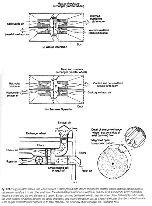
Enthalpy Wheels: The Best Options for IAQ Enhancement The enthalpy wheel is a cylinder, usually 4 to 10 inches deep, packed with a heat transfer medium that has numerous small air passages, or flutes, parallel to the direction of airflow. The flutes are triangular or semicircular in cross-section. The structure, commonly referred to as the honeycomb matrix, is produced by interleaving flat and corrugated layers of a high conductivity material, usually aluminum, surfaced with a desiccant. Stainless steel, ceramic, and synthetic materials may be used, instead of aluminum, in specific applications. The flutes in most wheels measure between 1.5 mm to 2.0 mm in height. The surface area exposed to airflow in a wheel lies between 300 to 3300 m2/m3, depending upon the configuration. In a typical installation, the wheel is positioned in a duct system such that it is divided into two half moon sections. Stale air from the conditioned space is exhausted through one half while outdoor air is drawn through the other half in a counter flow pattern. At the same time, the wheel is rotated slowly (2 to 20 RPM). Sensible heat is transferred as the metallic substrate picks up and stores heat from the hot air stream and gives it up to the cold one. Latent heat is transferred as the medium condenses moisture from the air stream that has the higher humidity ratio through adsorption by the desiccant (with a simultaneous release of heat) and releases the moisture through evaporation (and heat pick up) into the air stream that has the lower humidity ratio. Appendix 3: WECA Operations Manual |
||||||||||||||||||||||||||||||||||||||||||||||||||||
HOME | ABSTRACT | INTRODUCTION | HYPOTHESIS | METHODOLOGY | RESULTS | SUMMARY | REFERENCES"The Answer is Blowing in the Wind"A study of the Moss Street Childrens Center ARCH 591 Final Project University of Oregon For information please contact: Dennis Beyer [ dbeyer1(at)uoregon.edu ] Erik R. Bishoff [ ebishoff(at)uoregon.edu] Ady Leverette [ aleveret(at)uoregon.edu ] Brian O'Reilly [ boreilly(at)uoregon.edu] |
||||||||||||||||||||||||||||||||||||||||||||||||||||